KeyVision: The Programmable Visual Keyboard Project
[This is an excerpt from the original 1986 paper]
- Introduction
- Technical Aspects
- Hardware
- The LCDDIP unit
- The Programmable Visual Keyboard
- Software
- The SendCharacter() routine
- The SendFont() routine
- Hardware
- Economic Aspects
- Production Cycle
- Conclusion
1. Introduction
I find it interesting to go back to the moment that motivated a project; this is the naive realization that conceived KeyVision:
But this key shows the letter Z yet it types a W on the screen. Ah, your PC has the French keyboard installed. So, where is the Z?
summer 1984
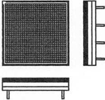
KeyVision describes the electronic counterpart of the mechanical keyboard stencil and key overlay. Today state of the art software relies on these archaic devices to indicate the function of the keyboard keys to the computer user; KeyVision replaces them by envisioning keyboards with a small programmable display on each key. This programmable display is part of a hybrid unit composed of a matrix LCD and an LSI chip assembled in a DIP (Figure 1-1). The LSI circuit incorporates a RAM, for storing the bitmap displayed on the matrix LCD, and an asynchronous finite-state machine with supporting circuitry for coordinating the unit I/O and displaying functions. This new keyboard type, Programmable Visual Keyboard (PVK), can be dynamically configured to show the purpose of the individual keys as the user navigates from one application to another or within an application. This document presents KeyVision.
Figure 1-1: Liquid Crystal Display 8-pins Dual in Line Package (LCDDIP)
It is appropriate to imagine how a PVK can be used before presenting the project technicalities; let’s consider the following:
- PVKs can be configured to show any alphabet, such as Arabic, Kanji, and Roman; thus, PVKs are country independent.
- The Roman alphabet has a variety of font types and styles (fonts types such as Helvetica, times and courier and font styles such as bold, italics and underlined), attributes that can be visualized on a PVK thus documenting at all times the currently selected font type and style.
- Key caps are not necessarily meant to show characters. CADs and games software, for instance, can benefit from having symbols instead of characters on the individual key faces of the keyboard (in a C.AD application there would be a key face showing a transistor, a couch, a camera, a circle… in a war game various icons indicating the different weapons and strategies could be shown). The special function keys, commonly found in extended keyboards, could contain icons symbolizing the keys functions, forever replacing the generic FI, F2… labels.
- Many of the functions that are currently on the screens of graphical user interfaces have also keyboard equivalents. On a PVK, depressing the appropriate special key could show the textual or iconic representation of the action.
- Studies have shown that there are better characters layouts for different countries, e.g. the letter A does not occupy the same location in the Italian and US keyboards, a PVK can simulate all of them (Characters location on keyboards are not standards even among the same alphabets, e.g., the Italian and American keyboard layouts differ.)
The objectives of the PVK are:
- provide a form of documentation at the keyboard level by elevating the keyboard from a dynamic input static output device to dynamic I/O device; and,
- maintain the keyboard mechanical touch and feel that many find pleasing (This objective is the criteria for not choosing devices such as touch screens which can very well emulate the first objective.)
2 Technical Aspects
This section details the project fundamental unit, the LCDDIP—its packaging and electronics—how it is employed to create a PVK, and the software to control it.
2.1 Hardware
2.1.1. The LCDDIP unit
The LCDDIP hardware description is presented in block, flow, state, and timing diagrams forms. An 8-pins DIP was chosen so that the unit may be easily used for other electronic applications. The following were the design objectives:
- The LCDDIP has the pin assignment shown in Figure 2-la. Pins 1 & 8 are both +V, pins 4 & 5 GND, the RESET(H) signal, fed into pin 2, is buffered before been sent to pin 7 (and viceversa), finally, the DATA(FI) signal (pin 3) is ANDed with the internal IDDefined(H) register before been sent to DATA(H) (pin 6) (and viceversa). For convenience we will refer to the Dataln(H) signal as the signal driving either pin 3 or 6, and DataOut(H) as the signal being emitted by pin 3 or 6, each unit has a Dataln(H) and a DataOut(H).
- LCDDIPs are cascaded as shown in Figure 2-1 b (see also Figure 2-9),
- An individual unit among a cascaded set can be addressed by a unique ID code assignable to each LCDDIP following a reset, and
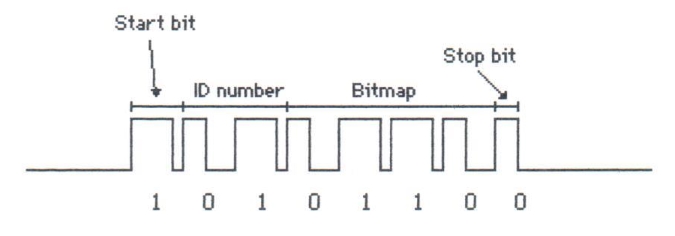
- The data is sent asynchronously on the DATA(H) line in packets composed of: a start bit (H), an ID number, a bitmap and a stop bit (L), see Figure 2-2. The 0 and 1 are coded as follows: DataIn rises to indicate the arrival of a bit of information, then DataIn settles and holds the bit value, see the top portion of Figure 2-4; the minimum time needed for the data to settle is indicated by ts and the maximum hold time is indicated by th.
Figure 2-1: (a) LCDDIP pin assignment, (b) Serial connection of LCDDIPs with Zapf Dingbats font shown.
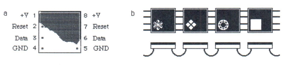
Figure 2-2: Data packet protocol. This simplified packet shows the four components of the protocol: a start bit, a 2-bits ID number, a 4-bits bitmap, and a stop bit.
[omitted text]
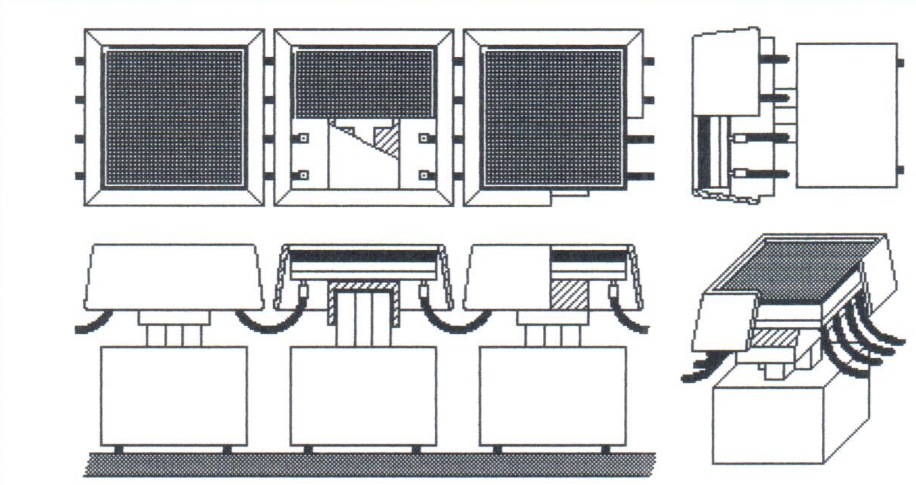
Figure 2-9: Sectional views showing how the LCDDIPs are interconnected in present day keyboards; note how the keyboard circuitry is not effected: the connections between LCDDIPs are suspendend.
[omitted text]
Last update 2018-12-11 06:29